Someone hands you ten sheets of drawings for your project, and every single one looks like a maze of lines to you. One's a bird's-eye view of your whole yard. Another's a bird's-eye view of just the rooms. A couple look like the front of a house. One looks like someone sliced the building open with a knife. They're all "architectural drawings," but they're not the same thing, and nobody explains what each one is actually for.
Here's the short version: a permit set uses several different types of drawings because a building is three-dimensional, and no single drawing can show everything a building department needs to verify. A site plan shows your whole property from above. A floor plan shows the inside layout, room by room. An elevation shows what the building looks like from the outside, straight on. A section shows a vertical slice through the building, revealing heights and structure you can't see from any other view. Each one answers a different question, and together they form a complete, coordinated picture of your project. Here's what each one actually shows and how they fit together.
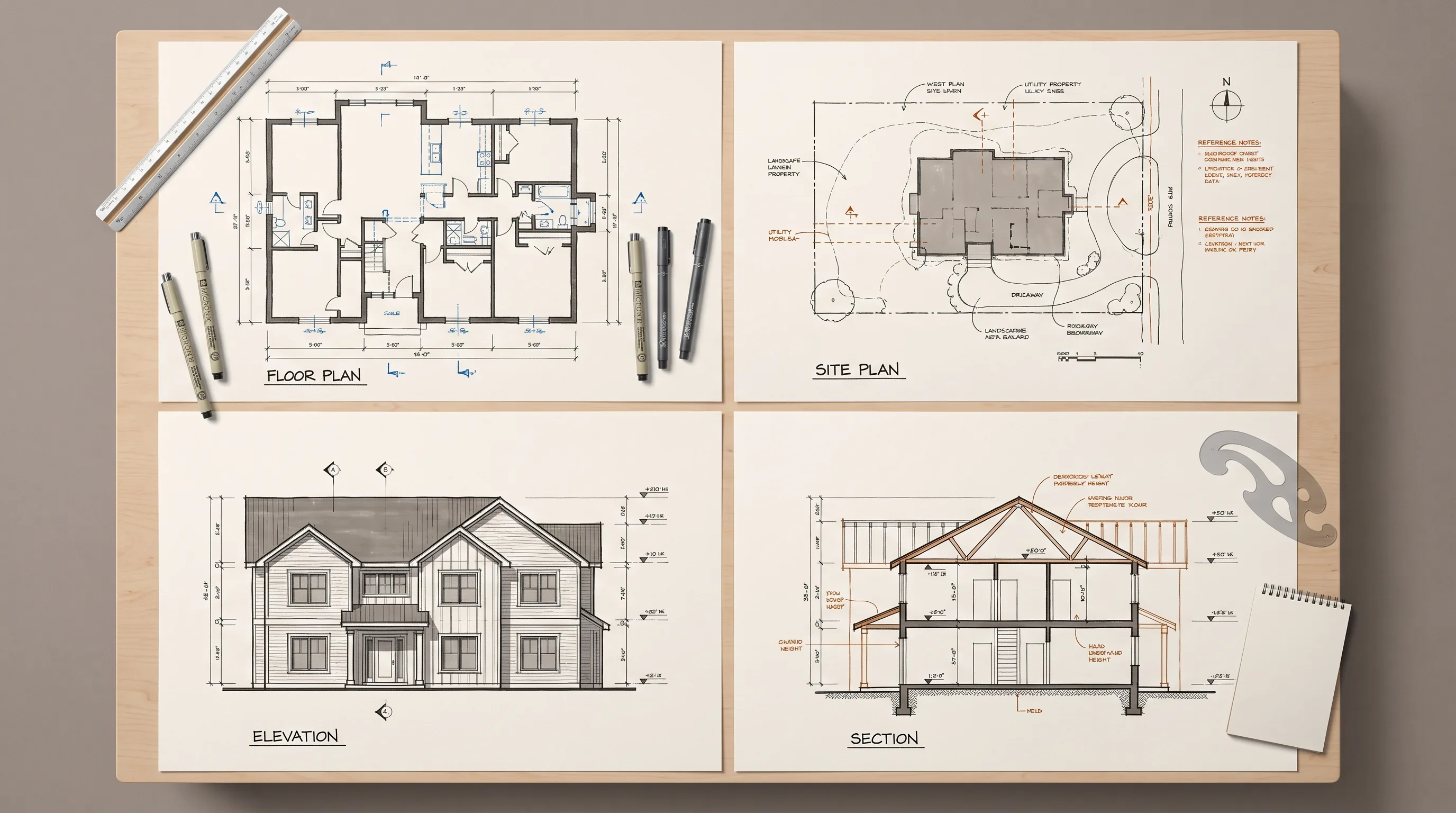
Below is a visual comparison showing all four drawing types for the same simple addition, including how a single window shows up consistently across three of them.
Why you need multiple drawing types
A building exists in three dimensions, and any single drawing can only show two of them at a time. So architects and drafters create several different views, each one answering a different question a building department needs answered before they'll approve construction.
Take a home addition as the example. The site plan answers: is it in the right place on the lot, and does it meet setback requirements? The floor plan answers: how does it connect to the existing house, and are the room sizes adequate? The elevation answers: how does it look from outside, and does it match the existing house? The section answers: what's the internal structure, how tall is it, and what are the actual floor-to-ceiling heights? All four questions matter, and no single drawing can answer more than one of them well.
Site plan: the property-level view
The site plan shows your entire property from directly above, property boundaries, your existing house, the new structure you're adding, setbacks, easements, utilities, and the surrounding streets. Picture yourself in a helicopter, 200 feet above your lot, looking straight down. That's what a site plan shows.
It's drawn at a zoomed-out scale, commonly 1"=10' to 30' depending on lot size, because its job is to show the whole property, not fine interior detail. Its purpose is verifying that your project complies with setback and zoning requirements, this is the drawing a plan checker reviews first, and it's the single most common source of permit rejection. For the full breakdown of what goes on this specific sheet, see What Is a Site Plan?
Floor plan: the room-level view
The floor plan shows the inside of the building from above, room layout, walls, doors, windows, fixtures, and dimensions. Imagine removing the roof and ceiling entirely and looking straight down at the rooms below. That's a floor plan.
Unlike the site plan, this is zoomed in, commonly drawn at 1/4"=1' to show real interior detail. Its job is verifying room sizes, circulation, fixture placement, and egress compliance. For an addition or remodel, you'll typically see two floor plans: the existing floor plan (what's there right now) and the proposed floor plan (what you're building), so a plan checker can see exactly what's changing.
Floor plan vs. site plan, in one line: the floor plan is inside the building and zoomed in; the site plan is outside the building, the whole lot, and zoomed way out.
Elevation: the facade view
An elevation shows what the building looks like when you're standing in front of it, looking at it straight on, heights, window and door placement, roofline, and exterior materials. Imagine standing in your yard looking directly at your house. That's an elevation.
Drawn at the same detail scale as the floor plan (commonly 1/4"=1'), an elevation verifies height compliance, exterior design, material specifications, and how the new work relates visually to the existing structure. A typical set includes four elevations, front, rear, left side, and right side, covering every face of the building.
Elevation vs. floor plan, in one line: the elevation shows how the building looks from outside (a vertical, facade view); the floor plan shows how the rooms are arranged inside (a horizontal, layout view).
Section: the cross-section view
A section shows a vertical slice through the building, interior heights, floor levels, roof structure, wall assembly, and foundation depth. Imagine cutting straight down through your house with a giant vertical blade and pulling the two halves apart to look at the exposed profile. That's a section.
Drawn at the same detail scale as the floor plan and elevation, a section verifies things no other drawing can show clearly: ceiling heights (most jurisdictions require a minimum around 7'6" for habitable space), roof structure, floor-to-floor heights, and insulation. A typical set includes at least two sections, one cut front-to-back, one cut side-to-side, to capture the building's full vertical profile from different directions.
Section vs. elevation, in one line: the section shows what's inside the vertical profile, structure, heights, layers; the elevation shows what the outside looks like, facade, materials, window placement.
How these drawings relate to each other
These aren't four separate, unrelated drawings. They're the same building, shown from four different vantage points, and that means they have to agree with each other.
Take a single bedroom window as an example. On the floor plan, you see the window's exact position along the wall and its width. On the elevation, you see the same window from outside, its size and placement on the facade. On the section, you see that same window's height off the finished floor and the ceiling height above it. Three drawings, one window, three different pieces of information about it.
Here's why this matters: if that window is shown as 3 feet wide on the floor plan but 4 feet wide on the elevation, that's an inconsistency, and it's exactly the kind of thing a plan checker catches and rejects. Every element that appears on more than one drawing has to be shown consistently across all of them. This coordination work is a real, deliberate part of preparing a permit set, not an afterthought, and not something that happens automatically just because one person drew all the sheets.
The complete drawing set
A typical residential permit set brings all of this together:
Property level:
- Site plan (setbacks, boundaries, easements)
Interior detail:
- Existing floor plan (what's there now)
- Proposed floor plan (what you're building)
Exterior views:
- Front elevation
- Rear elevation
- Left side elevation
- Right side elevation
Structural/detail:
- Sections (typically two, front-to-back and side-to-side)
- Detail sheets (enlarged views of specific connections)
Specialized, as needed:
- Electrical plan
- Plumbing plan
- Mechanical plan
- Structural drawings
That full collection is what makes up a complete permit set. See What Is a Permit Set? for how all of this fits into the broader submission and approval process.
| Drawing type | What it shows | Perspective | Typical scale | Purpose |
|---|---|---|---|---|
| Site plan | Whole property, boundaries, setbacks | Straight down, zoomed out | 1"=10'–30' | Zoning/setback compliance |
| Floor plan | Room layout, walls, doors, windows | Straight down, zoomed in | 1/4"=1' | Room sizes, egress, circulation |
| Elevation | Exterior facade, height, materials | Straight-on, eye level | 1/4"=1' | Height limits, design, materials |
| Section | Vertical slice, heights, structure | Cutaway profile | 1/4"=1' | Ceiling heights, structure, code |
How to read these drawings together
Start with the site plan. Find the property boundaries, locate the existing house, find the proposed addition, and check the setback dimensions against your city's requirements.
Move to the floor plans. Compare the existing floor plan to the proposed one, trace how the new space connects to the old, and verify room sizes and window/door placement.
Then the elevations. Match each elevation to the corresponding side of the building, and confirm that windows and doors shown on the floor plan actually appear on the elevation in the same positions.
Then the sections. Check where each section "cut" is taken relative to the floor plan, and verify ceiling heights and structural details.
Finally, do a coordination check. Does every door on the floor plan appear on the matching elevation? Do wall dimensions match between the floor plan and the elevation? Are room sizes consistent everywhere they're referenced? If anything doesn't line up, that's an error that needs fixing before submission, not something to catch after a rejection.
Common mistakes in coordinating drawings
Uncoordinated dimensions. A window shown as 3 feet wide on the floor plan but 4 feet wide on the elevation. This gets caught, and it gets rejected.
Missing dimensions on the floor plan. Rooms drawn without dimensions mean a plan checker can't verify minimum size requirements, an easy, entirely avoidable gap.
Elevations that don't match the floor plan. The floor plan shows three windows on a wall; the elevation shows two. Someone forgot to update one of the sheets after a revision.
Sections missing ceiling height dimensions. A section drawn without a labeled ceiling height means the one thing that sheet exists to verify isn't actually shown.
Missing scale. Any sheet submitted without a labeled scale can't be measured against by the plan checker, and gets sent back regardless of how accurate the underlying drawing actually is.
Every one of these is preventable with a real coordination pass before submission, someone checking every shared element across every sheet it appears on. See 7 Reasons Building Permits Get Rejected and Plan Check Corrections: How to Respond and Get Approved Faster for the broader picture of how these errors play out and how to fix them if they've already caused a rejection.
Which drawings you need, by project type
Not every project needs the full set. Here's how it typically breaks down.
| Project type | Site plan | Floor plans | Elevations | Sections | Other |
|---|---|---|---|---|---|
| Room addition | Yes | Yes (existing + proposed) | Yes | Yes | Structural if load-bearing changes |
| Bathroom/kitchen remodel (interior only) | Often not required | Yes | Sometimes (if finishes shown) | Rarely | Plumbing plan if fixtures move |
| Garage conversion | Yes | Yes | Yes | Yes | Structural, electrical, HVAC likely required |
| New deck | Yes | Rarely, a simple framing plan instead | Sometimes | Rarely | Framing/footing detail |
| New home | Yes | Yes | Yes (all four sides) | Yes (multiple) | Full MEP, structural, energy compliance |
For the fuller checklist by project type, see What Drawings Do You Need for a Building Permit?
FAQ
What's the difference between a floor plan and a site plan?
A floor plan shows the inside of the building, rooms, walls, doors, zoomed in. A site plan shows the entire property from above, boundaries, setbacks, the building's placement on the lot, zoomed way out. They answer completely different questions.
Why do I need an elevation if I have a floor plan?
A floor plan shows layout from above; it can't show height, roofline, window placement on the facade, or exterior materials. An elevation is the only drawing that shows what the building actually looks like from the outside.
What does a section drawing show?
A vertical slice through the building, ceiling heights, floor-to-floor heights, roof structure, and wall assembly. It's the only drawing that clearly verifies code-required ceiling heights and structural details that aren't visible from above or from the front.
How do I read an elevation drawing?
Match it to the side of the building it represents (front, rear, left, right), then check window and door placement, overall height, roofline, and materials, and confirm those windows and doors match what's shown on the corresponding floor plan.
Do I need all four drawing types for my project?
It depends on scope. A structural addition typically needs all four. A simple interior remodel with no exterior or structural changes may only need a floor plan, and sometimes not even a site plan. See the project-type table above, and confirm specifics with your building department.
How should drawings coordinate with each other?
Every element that appears on more than one sheet, a window, a door, a dimension, needs to match exactly across every sheet it appears on. This is checked deliberately during drawing preparation, not assumed automatically.
What if drawings have conflicting dimensions?
That's a coordination error, and it's one of the most common reasons a permit set gets rejected or sent back with corrections. It needs to be caught and fixed before submission, a plan checker will catch it if you don't.
Why do architects create multiple views of the same building?
Because no single drawing can show every dimension a building department needs to verify, location on the lot, interior layout, exterior appearance, and internal structure and height all require a different vantage point to see clearly.
Seeing the whole picture
Once you know what each drawing type is actually for, a permit set stops looking like a stack of confusing pages and starts looking like exactly what it is: the same building, documented from four angles, each one answering a specific question a building department needs answered. The thing that actually causes problems isn't any single drawing, it's when the four views stop agreeing with each other.
If you're preparing a set for your project, coordinating every drawing type against every other one, so a window, a wall, or a dimension never contradicts itself from one sheet to the next, is exactly the kind of quality check that prevents a rejection. Let us handle that coordination; you focus on your project. Start with permit drawing services.